Privacy statement: Your privacy is very important to Us. Our company promises not to disclose your personal information to any external company with out your explicit permission.
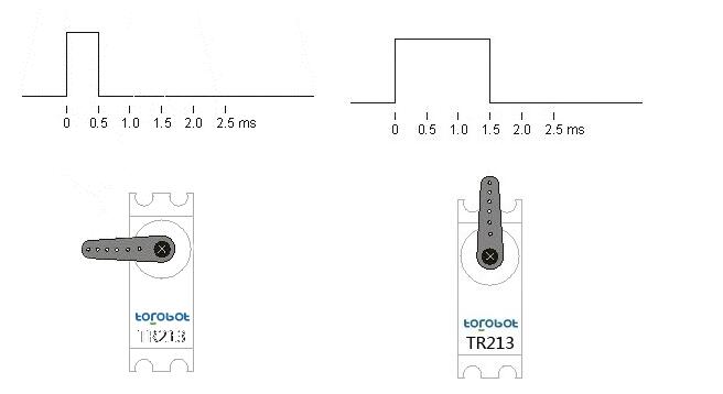
The servo control generally needs a time base pulse of 20ms. The high-level part of the pulse is generally an angle control pulse part in the range of 0.5ms to 2.5ms. Take a 180-degree angle servo as an example, then the corresponding control relationship is as follows:
0.5ms--------------0 degrees;
1.0ms------------45 degrees;
1.5ms------------90 degrees;
2.0ms-----------135 degrees;
2.5ms-----------180 degrees;
Please see the image description:

Each servo has its own parameters, such as TR213 servo operating voltage is 4.8-7.2V, TR205 servo operating voltage is 4.8-6V, the voltage can not exceed this range, otherwise it will easily burn the servo, It is recommended to use 5V to power the servo without knowing the operating voltage range of the servo.
The operating current of the steering gear is based on the actual conditions of the steering gear. For example, the TR213 steering gear has almost zero current when it is unloaded, and under normal load conditions, the current is about 0.5A, depending on the actual situation. . Six-legged robots need 18 TR213 metal servos. The current that needs to be increased is about 8A. If the power supply is insufficient, it will affect the performance of the servos. The most common phenomenon is that when one servo is loaded, other rudder opportunities appear chaotic. , irregularly swinging.
Servo wiring as shown below

The middle line of the 90% of the servos on the market is a positive one.
Basic knowledge introduced almost, you can go to Baidu look at the steering gear manual.
Here we talk about how to use the wiringPi library to drive the steering wheel to whatever you want in the Raspberry Pi. Why use the wiringPi library, because bloggers don't like to write Python, bloggers like to write c/c++ code. Do not talk nonsense, start.
First: First of all, I already know that the servo's pwm period is 20ms, and then it's like this
0.5ms--------------0 degrees;
1.0ms------------45 degrees;
1.5ms------------90 degrees;
2.0ms-----------135 degrees;
2.5ms-----------180 degrees;
That is to say it gives a high level of 1.5ms, and a low level of 19.5ms turns to 0 degree. It should be noted here that the position is 0 degrees, not the steering gear to 0 degrees, of course, if the steering gear is exactly at 0 degrees, of course, does not turn. There may be someone here who would like to ask. What position is it at 0 degrees? According to my understanding of the servo (180 degree servo), you are turning the servo in one direction to a place where you can't rotate. This position is not 0 degrees or 180 degrees. Then you can run it with the following code.

I am here to imitate pwm. When this code is run, the servo will automatically reach the 0 degree position.
Similarly, the code to move to the 45-degree position, the 90-degree position, the 135-degree position, and the 180-degree position is as follows:


Someone here might say that you don't use the delay() function because the delay function is accurate to milliseconds. When I pass 1.5 to it, and I pass it to it, you will find that the servos are all turning 45 degrees. Because of delay(int x), the precision is lost when 1.5 passes. (I made this mistake from the start, oh)
Here I think you should already know how to rotate 45 degrees, 90 degrees, and so on. Then you may find that the servo rotates too fast and may not be under your own control. Here I will give you an idea how to solve this problem.
Of course, my ability is limited, and it is hard to avoid mistakes in writing and I hope to correct me.
Here I give a very good link, you can go to see if you want to study in depth (he is using a microcontroller)
Http://
I think so. 0.5ms turn to 0 degrees, 1ms turn to 45 degrees, which one is not experienced 0.5ms, and turned 45 degrees, so I use 0.5 = 500us, 500us/45 degrees. Then it is about 11.11 us/degree.
Next my code is written like this.

In this way, the speed is indeed reduced, but each steering gear must first turn to 0 degrees before we can turn to the angular positions we have entered.
Raspberry Pi 3b+ control servo, servo motor drive code#include"stdio.h"
#include"wiringPi.h"
Void init();
Int main()
{
Init();
Int angle=0;
Scanf("%d",&angle);
Int i=0;
Float x=0;
Int k=180;//180 cycles is enough
While(k--)
{
x=11.11*i;
digitalWrite(15,HIGH);
delayMicroseconds(500+x);
digitalWrite(15,LOW);
delayMicroseconds(19500-x);
If(i==angle)
Break;
i++;
}
Return0;
}
Void init()
{
wiringPiSetup();
pinMode(15,OUTPUT);
}
Contactar proveedor

Privacy statement: Your privacy is very important to Us. Our company promises not to disclose your personal information to any external company with out your explicit permission.

Fill in more information so that we can get in touch with you faster
Privacy statement: Your privacy is very important to Us. Our company promises not to disclose your personal information to any external company with out your explicit permission.